Machining large-diameter bearing rings for wind turbine assemblies presents a set of workholding challenges that standard clamping methods handle poorly. The parts are heavy, the tolerances are tight, and the ring geometry — wide diameter relative to wall thickness — creates a distortion risk when clamping force is applied at discrete points around the perimeter. Any deformation introduced during clamping translates directly into dimensional error in the finished part, because the ring springs back toward its natural shape the moment the clamp is released. For machine shops and wind energy component manufacturers working through these problems, an electro permanent magnetic chuck offers a workholding approach that distributes clamping force across the full contact surface rather than concentrating it at jaw positions — and that difference in force distribution is what makes the approach worth examining in the context of bearing ring production.
What Wind Power Bearing Rings Are and Why They Require Precise Machining
Wind turbine bearing rings form the inner and outer races of the pitch and yaw bearings that govern blade angle adjustment and nacelle rotation. These bearings operate under substantial and variable loads — the combination of wind thrust, gravity, and dynamic forces from blade rotation — and they must maintain dimensional integrity across decades of field service with minimal maintenance access.
Raceway Geometry Is Non-Negotiable
The geometry of these rings is characterized by large outside diameters, relatively narrow wall sections, and precision raceway profiles on the internal or external faces. The raceway surface finish and form accuracy determine how the rolling elements seat, how load is distributed across the contact zone, and ultimately how the bearing performs under the operating conditions it encounters in service. A surface profile that deviates from specification at the machining stage cannot be corrected after assembly without disassembling and reprocessing the bearing — an operation that is neither practical in the field nor economical at the manufacturing stage.
Machining Challenges Specific to Large Ring Geometry
Why Thin-Wall Rings Distort Under Conventional Clamping
A thin-wall ring clamped at three or four jaw positions around its circumference deforms elastically inward at the clamped points and outward between them. The ring assumes a polygonal cross-section rather than a circular one while the clamping force is applied. Turning or grinding in this distorted state produces a surface that is circular relative to the distorted geometry — but when the jaws are released and the ring returns to its natural form, the machined surface reveals the distortion as out-of-roundness error.
The magnitude of this effect scales with the ratio of ring diameter to wall thickness. A ring with a large diameter and a thin wall section is more susceptible than a compact, heavy-walled ring, and the bearing rings used in wind turbines fall at the challenging end of this spectrum. Managing this distortion risk is not a peripheral concern in the machining of these parts — it is a central constraint that determines which workholding method is viable.
The Precision Requirements Around Raceway Geometry
The raceway profile on a bearing ring must meet tight form and finish specifications because it is a functional surface that directly influences bearing performance. The tolerance requirements for form accuracy — roundness, cylindricity, profile deviation — are tighter than for most other features on the same part. Achieving those tolerances requires not only a capable machine and cutting tool setup but a workholding arrangement that holds the ring stably and without induced distortion throughout the cutting cycle.
Interrupted cuts, heavy roughing passes, and the vibration associated with high material removal rates all impose dynamic forces on the workholding system. A clamping arrangement that holds adequately under light finishing passes may allow micro-movement under heavier cuts, which manifests as chatter marks on the raceway surface that are difficult to remove without an additional finishing operation.
Conventional Workholding and Its Limitations for Bearing Rings
JAW
Jaw Chucks and the Distortion Trade-Off
Three-jaw and four-jaw chucks are the standard workholding solution for ring-type parts in turning operations. They are versatile, quick to set up, and capable of holding a wide range of diameters without specialized tooling. Their limitation for thin-wall bearing rings is the concentration of clamping force at discrete jaw contact points, which produces the elastic distortion described above. Compensating for this distortion requires either accepting a wider form tolerance and performing a final finishing pass at reduced clamping force to remove the distortion-induced error, or using soft jaws machined to conform to the ring's outside diameter in order to increase the contact area per jaw. Neither approach fully resolves the problem. Soft jaws increase the contact area within each jaw but do not distribute the force around the full circumference. A reduced-force finishing pass limits material removal depth and may not achieve the required surface finish within the available cutting time.
FIX
Fixture Plates and the Setup Time Cost
For facilities running small batches of bearing rings at high accuracy requirements, dedicated fixture plates can be machined to match the outside profile of a specific ring diameter and used as a seating surface that supports the ring over a large area. This approach controls distortion more effectively than jaw chucks but introduces a different cost: the time and material required to machine a fixture plate that is specific to one ring dimension, and the need to manage an inventory of fixtures when multiple ring sizes are in production. For a facility producing a range of bearing ring sizes — which is common in the wind energy supply chain where different turbine classes require different bearing dimensions — the fixture plate approach creates an inventory and setup management burden that adds overhead to every job changeover.
How an Electro Permanent Magnetic Chuck Addresses These Challenges
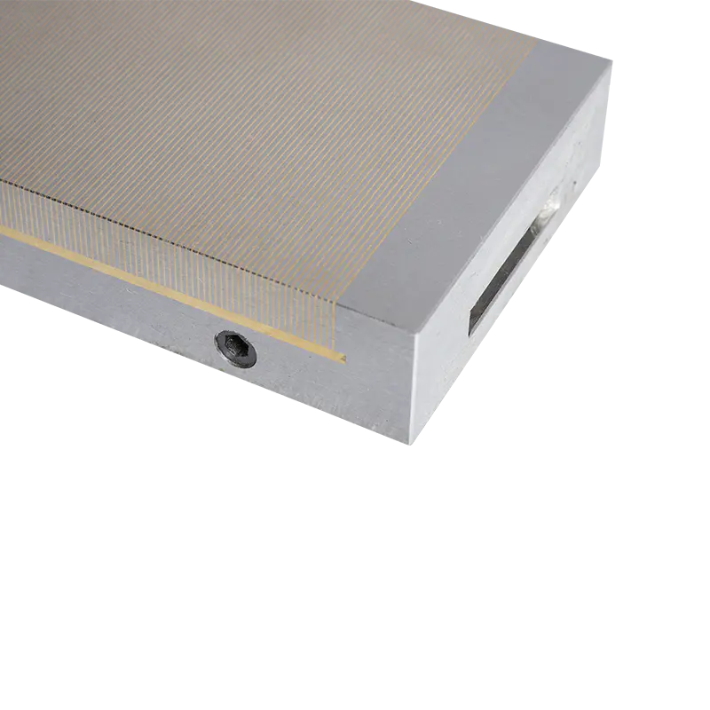
An electro permanent magnetic chuck holds ferromagnetic workpieces through magnetic flux generated by a combination of permanent magnets and electro-magnetic coils within the chuck body. The permanent magnets provide the holding force during the machining cycle without requiring continuous electrical power. The electro-magnetic coils are energized only to change the magnetic state — to activate or release the chuck. Once set, the holding force remains stable even if power is interrupted, which is a safety characteristic relevant in industrial machining environments.
The Critical Distinction
The critical distinction for bearing ring applications is the distribution of clamping force. A magnetic chuck holds the workpiece across its full contact surface rather than at discrete clamping points. For a ring placed on the chuck face, the magnetic force acts uniformly across the seated area of the ring base. This distributed force does not impose the point-load distortion that jaw-clamping produces, which allows the ring to remain in its natural circular geometry during machining.
How Distributed Magnetic Clamping Changes the Machining Outcome
Roundness and Cylindricity
When a bearing ring is held without induced distortion, the turning or grinding operation produces a surface that is circular relative to the ring's natural geometry rather than its distorted state. The roundness of the finished raceway reflects the capability of the machine tool and the cutting process rather than being degraded by the workholding. For facilities that have been achieving acceptable but not specification-compliant roundness results with jaw chucks, the shift to magnetic workholding often produces a measurable improvement in form accuracy without any change to the cutting parameters.
Vibration Damping
Magnetic workholding distributes the clamping force across the full contact area, which also distributes the reaction to cutting forces more evenly through the workpiece. A ring held magnetically resists the tendency to vibrate at its natural frequency during interrupted cuts or heavy passes, because the distributed holding force provides damping across the contact surface rather than allowing the ring to oscillate between jaw contact points.
This damping effect is most noticeable during roughing operations where material removal rates are high and cutting forces are variable. Reducing vibration during roughing protects the machine spindle, extends tool life, and produces a surface condition entering the finishing stage that requires less finishing stock removal.
Setup Time Reduction
A magnetic chuck with an appropriate pole pitch can hold a range of ring diameters without changing the chuck or machining new fixtures. The setup for a different ring size is reduced to placing the ring on the chuck face and activating the clamping cycle. For facilities running multiple ring sizes in the same production period, this flexibility reduces the setup time between jobs compared to fixture-plate approaches, and eliminates the fixture inventory management that dedicated mechanical fixtures require.
Comparing Workholding Methods for Wind Power Bearing Ring Machining
| Criterion |
Jaw Chuck |
Soft Jaw Chuck |
Fixture Plate |
Electro Permanent Magnetic Chuck |
| Distortion Risk |
High for thin-wall rings |
Moderate |
Low |
Low |
| Clamping Force Distribution |
Point loads at jaws |
Improved at jaw zone |
Area contact |
Full-surface distributed |
| Setup Time per Ring Size |
Fast |
Moderate (jaw preparation) |
High (fixture machining) |
Fast |
| Flexibility Across Sizes |
High |
Moderate |
Low |
High |
| Vibration Damping |
Low |
Low to moderate |
Moderate |
High |
| Power Required During Cut |
None |
None |
None |
None (permanent magnets hold) |
| Safety on Power Loss |
N/A |
N/A |
N/A |
Maintained (permanent magnet) |
| Investment Cost |
Low |
Low |
Moderate |
Higher upfront |
The table reflects the trade-offs that influence workholding selection for bearing ring production. The electro permanent magnetic chuck carries a higher initial investment than mechanical alternatives, but its combination of distributed clamping force, setup flexibility, and vibration damping addresses the specific challenges of large thin-wall ring machining in a way that mechanical approaches require workarounds to approximate.
Which Machining Operations Benefit from Magnetic Workholding?
TURN
Turning Operations on Ring Faces and Bores
Face turning and bore machining are the primary operations in bearing ring production where the distortion risk from jaw clamping is most consequential. The raceway profile is machined in these operations, and the form accuracy requirements are tightest here. Magnetic workholding allows these cuts to be made with the ring in its natural geometry, which directly improves the achievable form accuracy without requiring the compensation strategies that jaw-clamped setups use.
GRIND
Grinding and Finishing Operations
Grinding operations on raceway surfaces operate at lower cutting forces than turning but require the ring to hold its position with minimal vibration across extended grinding cycles. The damping effect of distributed magnetic clamping is particularly beneficial in grinding, where vibration at the grinding interface produces surface finish defects that are difficult to remove without additional grinding passes. For facilities that turn and grind bearing rings in separate operations, magnetic workholding in the grinding stage provides consistent positioning repeatability between setups, which reduces the variation in finished part dimensions that accumulates when parts are repositioned between operations.
DRILL
Drilling and Tapping Bolt Circle Features
Bearing rings typically include bolt circle features — drilled and tapped holes for assembly attachment — that are machined after the raceway and bore operations. Magnetic workholding allows these secondary operations to be performed on the same chuck setup if the machine configuration permits, reducing the number of repositionings and the dimensional variation that each repositioning introduces.
Selecting a Magnetic Chuck for Wind Energy Bearing Ring Production
The selection of a magnetic chuck for bearing ring applications involves several parameters that should be evaluated against the specific ring dimensions and machining operations in the facility:
- Chuck diameter and ring interface area — the chuck must be large enough in diameter to support the ring at its contact zone without the ring overhanging the chuck face
- Pole pitch — the spacing of the magnetic poles across the chuck face determines how uniformly the clamping force distributes across a given ring width; a pole pitch appropriate for the ring wall thickness is necessary to generate adequate holding force in the contact zone
- Holding force per unit area — the magnetic holding force must be sufficient to resist the cutting forces and the vibration forces generated during the intended machining operations
- Thermal behavior — prolonged machining generates heat that can affect the magnetic properties of the chuck body; chucks designed for continuous production environments incorporate thermal management features that maintain consistent clamping force across extended machining cycles
- Interface with machine tool — the chuck must mount to the machine table or faceplate in a configuration that maintains its flatness and concentricity within the tolerances required for the bearing ring application
Production Efficiency Considerations for Bearing Ring Facilities
Wind energy component production typically involves a range of bearing ring sizes corresponding to different turbine classes. A facility that processes multiple ring sizes benefits from workholding equipment that does not require size-specific fixturing, because the setup time saved across a production schedule with frequent size changes is a material contribution to overall throughput.
Single-Setup Roughing and Finishing
Magnetic workholding also supports the trend toward tighter integration of roughing and finishing operations in a single setup. A ring that can be rough-turned and finish-turned on the same chuck, without repositioning between operations, eliminates the repositioning error that accumulates when the part is re-chucked between stages. For bearing ring dimensions where the tolerance on raceway runout relative to the bore is tight, eliminating the repositioning step between turning operations removes a source of variation that is otherwise difficult to control.
Supplier Evaluation for Industrial Magnetic Workholding
For machine shops and wind energy component manufacturers evaluating magnetic workholding systems, the supplier evaluation should go beyond unit price and nominal holding force specifications. The relevant evaluation criteria include the manufacturer's experience with large-diameter ring applications, their ability to provide application engineering support during setup and qualification, the availability of replacement components for long-term service, and whether the chuck design allows repair and recalibration without returning the entire unit to the manufacturer.
A magnetic chuck specified for wind energy bearing ring production is a capital investment that should remain in productive service across multiple production programs. The quality of the chuck body construction, the consistency of the magnetic pole layout, and the thermal stability of the design under sustained production conditions all affect how the chuck performs over its service life relative to its initial specifications.
About the Manufacturer
Zhejiang Three-gold Magnetic Machine Co., Ltd. manufactures electro permanent magnetic chucks and related magnetic workholding systems for precision machining applications, including large-diameter ring and disc components in the wind energy and heavy equipment sectors. For engineering teams evaluating magnetic workholding for bearing ring production, or procurement teams comparing specifications for a new or replacement chuck program, contacting the technical team with part dimensions, machining operation details, and machine tool configuration provides the basis for an application-specific recommendation rather than a generic product selection.


 English
 中文简体
中文简体
 русский
 عربى
عربى