Permanent magnetic chucks are widely used to hold ferrous workpieces during grinding, milling, turning, EDM, and other machining jobs. They provide a secure way to position steel and iron parts without putting mechanical clamps across the cutting area.
When buyers compare magnetic chucks, they often look at holding force, chuck dimensions, or maximum magnetic capacity. Those numbers matter, but they don't tell the whole story. The magnetic pole design inside the chuck also has a direct effect on how the workpiece is held.
Pole pitch, pole width, pole shape, magnetic circuit layout, and the way magnetic force is spread across the surface all affect actual performance. A chuck made for thin sheet material, for example, may use a very different pole arrangement from one designed for heavy milling.
For machine tool manufacturers, distributors, and industrial buyers, understanding these details makes product selection a lot easier. It also helps avoid buying a chuck that looks suitable on paper but doesn't behave as expected on the machine.
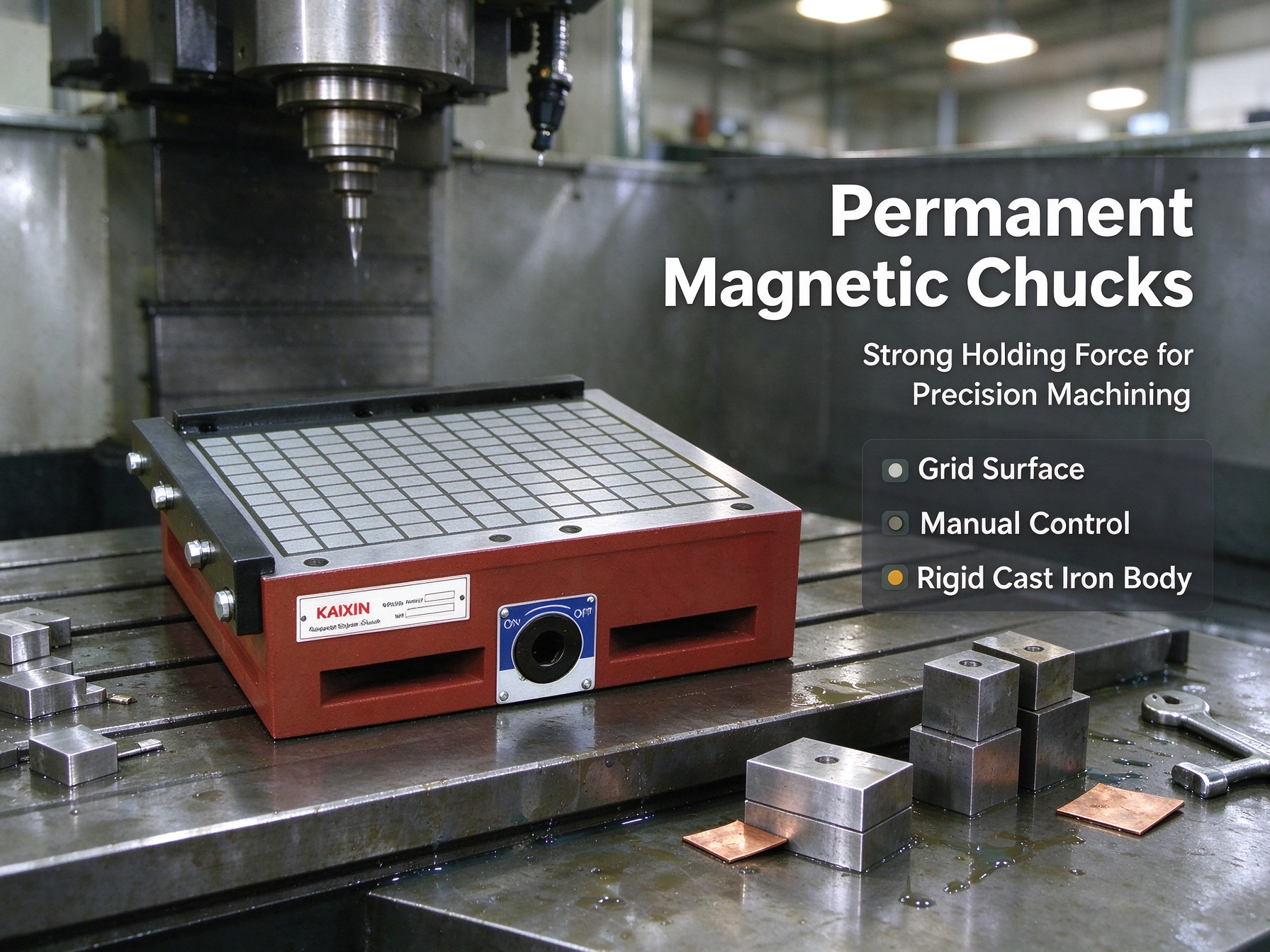
Magnetic poles are the areas on the chuck surface where magnetic flux reaches the workpiece. They are generally arranged with alternating north and south poles so that the magnetic field can pass through the workpiece and complete its circuit.
The spacing between neighboring poles is usually called pole pitch. Pole width and the non-magnetic spaces between the poles are also part of the design.
Put simply, these dimensions decide how the magnetic field is spread over the chuck surface. Change the layout, and the way the chuck interacts with the workpiece changes too.
A basic permanent magnetic chuck may contain:
These parts don't work independently. Together they form the magnetic circuit, so changing one part of the pole structure can affect the behavior of the whole chuck.
Pole pitch is one of the main design variables in a magnetic chuck.
A smaller pole pitch means the magnetic poles are closer together. This can be useful for thin or relatively small workpieces because the magnetic field can interact with more of the available material.
A larger pole pitch creates a different magnetic field pattern and can be useful for thicker workpieces where deeper magnetic penetration is more important.
Still, smaller doesn't automatically mean stronger. That's a common assumption, but it isn't that simple.
Actual holding performance depends on workpiece thickness, material, permeability, surface condition, and how much of the workpiece is actually in contact with the chuck.
| Pole design factor | General influence |
|---|---|
| Smaller pole pitch | Can improve magnetic interaction with thinner parts |
| Larger pole pitch | May support deeper flux penetration in suitable workpieces |
| Wider magnetic poles | Can provide larger contact regions |
| Narrower poles | Create more concentrated field distribution |
| Larger non-magnetic gaps | Affect flux concentration and circuit efficiency |
| Alternating pole layout | Establishes the magnetic circuit across the workpiece |
These points are useful for comparison, but actual magnetic performance still needs to be checked with the specific chuck and workpiece.
Thin steel parts can be more difficult to hold consistently than thick blocks.
If the chuck is designed around a much thicker workpiece, part of the magnetic field may not interact effectively with a thin sheet. A closer pole arrangement can spread the magnetic influence across the material that is actually available.
This can be useful for surface grinding thin steel plates, precision components, and sheet-like parts.
There is another issue with thin workpieces: deformation. A thin part can move or flex under machining forces. A suitable pole pattern can spread holding force over a larger area and help reduce localized movement.
That said, magnetic workholding can't remove every source of deformation. Workpiece flatness, internal stress, thickness variation, and machining conditions still matter. The chuck is only one part of the setup.
Magnetic holding isn't only about what happens at the contact surface.
The magnetic field needs to travel through the workpiece to create a useful holding force. Because of that, workpiece thickness and magnetic properties have a direct effect on how well the field can do its job.
For thicker workpieces, pole geometry can be designed to provide more effective magnetic penetration. This can become important during heavier machining, where larger cutting forces are transferred into the workpiece.
A buyer should therefore tell the manufacturer the usual workpiece thickness before choosing a chuck.
Without that information, it's easy to end up with a magnetic circuit that isn't well matched to the actual parts being machined.
Pole width affects the amount of magnetic material exposed at the chuck surface and changes the way the field spreads around the workpiece.
Wider poles can create broader magnetic contact areas. Narrower poles produce a more segmented pattern, with the magnetic influence concentrated into smaller regions.
Which one works better depends on the job.
Precision grinding may benefit from a different pole arrangement than rough milling because the forces involved are different. Workpiece geometry matters too. A large flat plate gives the magnetic field plenty of contact area, while a narrow bar or irregular part may interact with the poles in a much less even way.
This is one reason magnetic chuck manufacturers offer different pole patterns instead of using one surface design for every model.
Holding force gets most of the attention, but stability is just as important once machining begins.
A milling cutter or grinding wheel can create sideways, upward, and rotational forces. The magnetic pole layout helps spread the holding force over the area where the workpiece is actually supported.
When only a small portion of the part has effective magnetic contact, the workpiece may be more likely to shift, especially if it is long, narrow, or irregular.
A suitable pole layout helps the magnetic field interact with enough of the workpiece to support stable positioning while still leaving the working area accessible to the machine tool.
Different metals react differently to magnetic fields.
Many carbon steels are strongly ferromagnetic and are generally well suited to permanent magnetic workholding. Some stainless steels can also be magnetic, while others have little magnetic response. Aluminum, copper, and brass generally do not work with conventional magnetic chucks.
Even within steel materials, magnetic behavior can change with composition and material condition.
So pole design shouldn't be judged separately from the workpiece material.
| Workpiece characteristic | Effect on chuck selection |
|---|---|
| Strongly magnetic steel | Usually suitable for magnetic workholding |
| Magnetic stainless steel | Performance depends on grade and condition |
| Non-magnetic stainless steel | Limited magnetic response |
| Aluminum | Not suitable for conventional permanent magnetic holding |
| Brass or copper | Generally non-magnetic |
| Thin steel sheet | Requires attention to pole pitch and flux distribution |
| Thick steel blocks | Greater emphasis on force depth and machining load |
When the material grade is uncertain, a practical material test can prevent a lot of guesswork.
A magnetic circuit generally works better when there is close contact between the workpiece and chuck surface.
Even a small air gap can reduce magnetic coupling. Rust, scale, chips, paint, dirt, uneven surfaces, or a warped workpiece can create that gap.
This is why a chuck with a high rated holding force may still provide less practical holding force in the workshop.
Keeping the chuck surface clean and making sure the workpiece sits properly against the pole surface are basic but important maintenance steps.
The pole arrangement can help with certain surface conditions, but it can't completely compensate for a large or uneven air gap.
The machining process should always be part of the chuck selection discussion.
Surface grinding usually involves fairly flat workpieces and places a strong focus on stable holding and minimizing unwanted movement.
Milling creates more noticeable lateral cutting forces, so the chuck needs a magnetic circuit and structure that can resist movement during cutting.
EDM or precision machining may place greater emphasis on accurate positioning, repeatability, and keeping the workpiece accessible.
Heavy machining can call for stronger structural construction and a pole pattern suited to thick, heavy workpieces.
For distributors, simply asking what size chuck a customer needs may not be enough. Asking how the chuck will actually be used can lead to a much better recommendation.
A magnetic chuck should provide reasonably consistent holding across its working surface.
If the field is uneven, some parts of the workpiece may be held firmly while other areas contribute much less to overall stability.
Manufacturers can adjust pole dimensions and other magnetic circuit components to create a field distribution that suits the size and purpose of the chuck.
This becomes more challenging as chuck size increases. A larger working area needs more consistent magnetic performance across the full surface.
When purchasing large-format Permanent Magnetic Chucks, buyers should therefore ask about field distribution and recommended workpiece coverage instead of looking only at the highest holding force figure.
The pole pieces are only part of the magnetic circuit. The permanent magnets behind them also influence how much magnetic field the chuck can produce.
Different magnet materials can have different magnetic properties, temperature behavior, space requirements, and costs. Depending on the chuck construction, manufacturers may use neodymium or other permanent magnet technologies.
But magnet grade alone doesn't determine the final holding force.
The magnetic circuit, pole geometry, magnetic path, air gap, workpiece material, and workpiece thickness all contribute to the result.
That explains why two chucks with similar external dimensions can show noticeably different performance in actual machining.
Permanent magnetic chucks don't normally need continuous electrical power to maintain their magnetic holding state. That can be convenient in a machine shop, especially where a constant electrical connection isn't desirable.
However, heat is still something to consider.
Grinding and cutting generate heat in the workpiece and surrounding equipment. Changes in temperature can affect workpiece dimensions and, depending on the chuck design and magnet material, may also influence magnetic behavior within the specified operating range.
For precision grinding, buyers should look at coolant conditions, temperature control, chuck flatness, and the thermal behavior of the workpiece as part of the overall setup.
When sourcing magnetic chucks, buyers should give the manufacturer enough information to connect the chuck design with the real machining job.
Useful questions include:
These questions help buyers see beyond a single holding-force number and understand how the chuck is expected to perform in actual use.
A sample test often tells you things a catalog specification can't.
The test workpiece should be close to the parts used in production, including material grade, thickness, surface condition, and dimensions. The chuck can then be checked under machining conditions that are reasonably close to the final application.
Useful things to watch include:
For OEM projects and repeat purchases, recording the approved chuck configuration and test conditions also gives both sides a clear reference for future orders.
A good magnetic design still depends on accurate manufacturing.
Pole height, surface flatness, separator dimensions, magnet position, and machining tolerances can all affect the magnetic circuit and the final workholding result.
Manufacturers of industrial magnetic chucks should therefore inspect both dimensional accuracy and magnetic performance.
Typical checks may cover surface flatness, pole dimensions, operating mechanism function, appearance, and magnetic holding force.
For precision machining, mounting accuracy matters too. Even a well-made chuck can cause positioning issues if it isn't installed or finished correctly on the machine.
Magnetic pole design has a direct effect on how Permanent Magnetic Chucks hold different workpieces. Pole pitch, pole width, magnetic circuit layout, and field distribution can all influence holding force, stability, magnetic penetration, and the chuck's suitability for thin or thick materials.
There isn't one pole pattern that fits every machining job. Thin steel sheets, heavy blocks, precision grinding parts, and irregular workpieces can all place different demands on the magnetic circuit.
For B2B buyers, the practical approach is to start with the actual workpiece and machining process, then compare the chuck design against those conditions. Looking at pole specifications, rated holding force, test conditions, and sample performance gives a much clearer picture of whether the chuck will work properly once it reaches the production floor.



PRODUCTS

CONTACT US
Copyright @Zhejiang Three-gold Magnetic Machine Co., Ltd. All rights reserved
Magnetic Lifting Tools Manufacturers


 English
 中文简体
中文简体
 русский
 عربى
عربى